Tim Richardson has been involved with the Raspberry Pi community from almost the start. He is part of the Pi Wars organising team and a course designer/builder, as well as writing the CamJam EduKit worksheets, CamJam organiser, and now a PCB designer.
After seeing his first 3D printer at a Raspberry Jam back in 2014, Tim Richardson bought one. They were just starting to become affordable, albeit £600 for a ‘budget’ one back then! They are much more affordable now, as little as £150–£200 for a decent one. He has some advice for those new to or thinking about getting one.
See also
3D printing and making in The MagPi magazine 97
Use a 3D printer with Raspberry Pi
OctoPrint
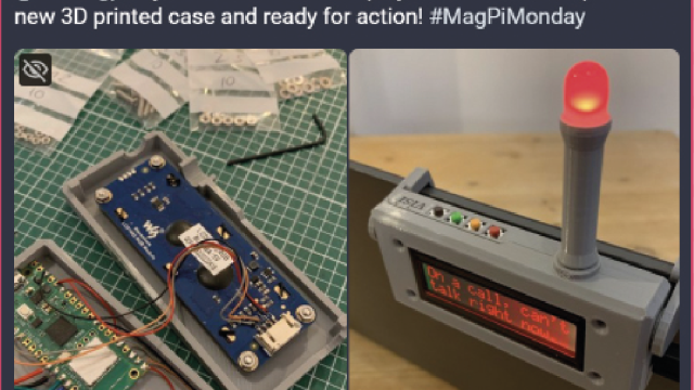
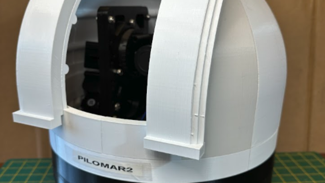
Tim suggests that one of the best upgrades you can do is to add a Raspberry Pi computer running OctoPrint. It’s free and open-source and has been continuously developed by Gina Häußge since 2012. OctoPrint is used to control and monitor your printer, even remotely, and uses a Raspberry Pi Camera Module for creating a time-lapse video of your prints..
OctoPrint runs on almost any Raspberry Pi computer, but you will get the best UI response from a Raspberry Pi 3 or newer.
OctoPrint supports most consumer printers on the market, so it is likely to work with yours. Installation is a breeze! Just download OctoPi, an OS image with OctoPrint pre-installed, write it to a microSD card, boot up, connect your printer, and that’s it!
Once you have set up OctoPrint for your printer, you can start moving the print head around (essential for bed levelling) and see the temperature of your print bed (if it is heated) and the extruder.
During printing you can watch the temperatures, see the G-code as it is executed, and watch the progress of the print on your phone or computer.
Tinkercad
Tim uses Tinkercad for most of his designs; it’s simple and easy to use. He has a few tips which may help you design objects in this online tool from Autodesk.
On starting a new design, add the ruler to the workplane. Every selected shape will show dimensions which can be edited with exact sizes. This even works for rotation.
When designing a mount or case for something, Tim first models the item itself, simplified but accurately measured. He places solid blocks where ports or buttons need to be accessed. He then enlarges the model by 1 mm in each direction. After that, he changes the shape to be a ‘hole’ and uses it to remove material from simple blocks.

Laser cutting with Raspberry Pi
Laser cutters are the mainstay of almost all makerspaces. Tim is fortunate enough to have a large one of his own that he uses for building Pi Wars courses, but for most people the smaller cutters are more than enough, and cost around £300. Tim has a few bits of advice if you are using one for the first time.
Laser cutters can be used for plastic, wood, and other materials. Some plastics just melt or burn, while some wood is hard to cut and you may end up breaking Rule Zero (don’t be on fire). Only buy materials designated as laser safe.
Before cutting expensive materials, always do a test cut in cardboard first. While the thickness will usually not be right, you will be able to line up all the holes to ensure that everything fits. There is nothing more frustrating than carefully designing something only to find that it won’t fit together, or you cannot bolt your Raspberry Pi computer in place because you have forgotten about the space the cables take!
Inkscape is a free and great tool to start with, which of course runs on Raspberry Pi. However, for some cutters the SVG files have to be exported to a different format. Dominic Morrow, from Smoke and Mirrors, recommends using Lightburn. It is commercial software, but updated regularly. It is able to connect directly to many laser cutters and control them, all in one tool. Inkscape does have some specific plug-ins which are very useful, though – especially the ‘living hinge’ tool for cutting ‘bendable’ wood and plastic.
PCB design with Raspberry Pi
Before Raspberry Pi, Tim knew nothing about electronics. Since Raspberry Pi, though, he has brought out three CamJam EduKits to help others learn. Tim says, “It helped that I knew nothing when writing the worksheets as I had to explain things in a way that noobs would understand.”
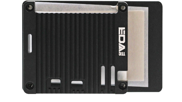
He thought PCBs were something he could never do, but reading an article in HackSpace magazine gave him an idea. For Tim, the height of a Raspberry Pi Zero with micro-HAT (μHAT) was higher than he wanted; how about mounting a Raspberry Pi Zero and μHAT on the same plane?
He found a μHAT template for KiCad (an open-source tool for designing PCBs) which has a single header and holes in place. With a second header, surely it was a simple case of ‘joining the dots’? Not quite – it’s advisable to connect all ground pins together. Tim had to move tracks to give space for ‘vias’ (channels that go between layers of the PCB).
Once confident the connections were correct, it was time for manufacture. Tim searched for PCB makers, but for a simple board he didn’t want to pay much. PCBWay had an easy-to-use interface and instructions on preparing KiCad designs for manufacture.
PCB design tips
While waiting for the first PCB to be manufactured, Tim started designing the second. He wanted to control WS2812 LEDs (aka NeoPixels) with Raspberry Pi.
When designing a PCB, you first have to find components that do what you want. For WS2812 LEDs, the 3.3 V from the
GPIO pins must be increased to 5 V. The 74HCT125 chip has four ‘level shifters’ for that. The next task is to breadboard the circuit, and write code to control the electronics – open‑source software can help with this.
Before designing the PCB, you have to design the schematic diagram: how each component connects to other components. It doesn’t have to be pretty, but it has to have all the right connections.
Often, specific GPIO pins have to be used. Other pins seem to be logical on the breadboard, but when routing the tracks on the PCB you may find it is not quite as simple! “Be ready to change the design multiple times to make routing of tracks easier,” Tim advises. If you have to make any changes during the PCB design, always go back and rework the breadboard. Eventually Tim got a PCB that looked like it would work. He showed the design to some friends – an invaluable part of designing a PCB. For Tim, they suggested he should break out unused pins and add a button for turning Raspberry Pi off.
After a redesign, Tim asked a PCB expert to check it. They came back with lots of advice. Firstly, protect the Raspberry Pi computer from powering the LEDs. It cannot supply much current, so a Schottky diode between the PCB’s power input and Raspberry Pi will stop that. There were ‘unsightly gaps’ on the PCB; the ground plain did not flow into spaces where tracks were too close. They also advised capacitors to help smooth power supply fluctuations, as well as button ‘bounce’ for the off button.

Tim says, “Designing PCBs takes multiple iterations, especially if it is your first. Even experts don’t get it right the first time.”
He ordered this second PCB from PCBWay and, with the express service, had the new boards within a week! However, as often happens, things were not perfect. Tim had placed the silk screen (printing) over components on the bottom of the board. A simple cosmetic mistake, fortunately.
“I soldered the first PCB and… it didn’t work,” he recalls. “Raspberry Pi Zero did not boot.”He tested the supply and then, with a multimeter, worked through the PCB. The barrel jack had power, but the ground was the wrong leg! The ‘footprint’ Tim used was not the same as the physical jack.
Fortunately, the fix was simple: soldering a wire between the ground and mounting pins was all that was needed. The rest worked perfectly!