HATs first arrived with the launch of the Raspberry Pi Model B+ in 2014. Since then, there have been some amazing and wonderful HATs, many of which have featured in previous issues of The MagPi: theUnicorn HAT, Piano HAT, Sense HAT, and Explorer HAT. Officially, HAT stands for ‘Hardware Attached on Top,’ although your expert suspects that the acronym came after the name. What else would you call an add-on board that sits on top of the Pi?
The full article can be found in The MagPi 42 and was written by Richard Hayler
Although you can manufacture and sell boards that don’t conform to the HAT standard, there are many advantages in doing so. Having the same physical dimensions makes it easy to ensure your board will fit with most Pi cases, and the inclusion of an EEPROM allows the operating system to identify the HAT and set up any required hardware at startup.
You'll need
An EEPROM (a CAT24C32 is recommended)
A breadboard and some jumper leads
he Pi HAT specification repository
These instructions will work with either the latest version of Raspbian (Jessie) or the older Wheezy. As usual, run a sudo apt-get update and sudo apt‑get upgrade before starting. Then enable kernel support for I2C using:
sudo raspi-config
Choose ‘Advanced Options’, then tap down and select ‘A7 I2C’. Make sure ‘Yes’ is highlighted for the answers to both questions. Alternatively, if you’re using Jessie, you can set this up using the Raspberry Pi configuration tool available through the GUI.
You will then be prompted to reboot. Once your Pi has restarted, install the I2C tools package with:
sudo apt-get install i2c-tools
Now it’s time to construct your EEPROM circuit on a breadboard. Put together the circuit as shown below. If you’re not using a 24C32, you may need to connect to different pins for SDA and SCL. Check the data-sheet for your IC to make sure you get this correct. You also need to give the HAT some functionality: in the interests of keeping things simple, the circuit of Fig 1 just contains a tri-colour RGB LED, but you can use whatever components you wish, depending on what you want your HAT to do.

Power up the Pi. You may notice that the LED is already on (perhaps just faintly). This is because the Pi doesn’t know what is connected and so the GPIO output is ‘floating’. This is something our HAT will deal with by preconfiguring the pins that it uses. The code snippet at the end of this tutorial provides some simple Python for interacting with the LED; you’ll need to install the wonderful gpiozero library to use it.
Next, check to see what I2C devices have been detected on the second I2C bus:
i2cdetect -y 1
You should see a table displaying the devices found on your I2C bus. Assuming you have nothing else connected, all but one of the entries should be empty, as represented by 2 dashes: – –. Normally, your EEPROM should show up in the leftmost column (0) as the number 50, next to the 50 on the horizontal axis.
If you don’t see this or the command returns an error (‘No such file or directory’), try the other bus:
i2cdetect -y 0
If your EEPROM still isn’t showing up, check your connections and that you have I2C support enabled.
Now you need some software. Clone the HATs reference material and tools from GitHub. It’s well worth reading this documentation, as it explains the thinking behind the HAT specification in lots of detail.
You’re also going to use the handy EEPROM tools to flash your chip. First of all, compile the eepmake tool:
cd hats/eepromutils
make
Then modify the eepflash script, which assumes that the EEPROM is on the first I2C bus; if yours is, then you can obviously skip this step. Copy the eepflash.sh and then modify with your favourite text editor:
cp eepflash.sh eepflash1.sh
nano eepflash1.sh
Change all mentions of i2c-0 to i2c-1, and i2c-0/0-0050 to i2c-1/1-0500, then save the file.
Now you need to modify the supplied template with your own settings. Open the eeprom_settings.txt file in your favourite editor and modify the various fields. Most are self-explanatory and you can read more about each one in the specification. However, the UUID is particularly important and must comply to RFC 4122, so that every HAT can be uniquely identified and can therefore be used as a per-board serial number. It also allows HATs to be stacked.
Once that’s done, you need to convert the human-readable text file into binary data that can be written to the EEPROM.
./eepmake eeprom_settings.txt eeptest.eep
Then dump this data to the EEPROM - this is the actual flashing bit and you’ll see a warning asking you if you’re sure you want to go ahead:
./.eepflash1.sh -w -f=eeptest.eep -t=24c32
Make sure you use the version of the script we modified earlier. If you’re using a different type of EEPROM, change the -t parameter accordingly.
To test your new creation, you need to modify your circuit so that the EEPROM is connected to the Pi as it would be if it were part of a HAT. GPIO pins 27 and 28 are reserved for HAT detection, so power down your Pi again and move the appropriate wires as shown below. Then add the 3.9kΩ pull-up resistors which ensure that the pins are not ‘floating’.

Now reconnect the power to your Pi and let it boot. If everything has worked, the directory /proc/device‑tree/hat should be present, and the contents of its files should match the details in the default eeprom_settings.txt file. You should also see that the GPIO pins used by the RGB LED have now been preset, so it should not be lit at all.
Congratulations! You have now programmed an EEPROM that the Pi recognises as meeting the specification for a HAT.
As a final test, run the myoh-rgb.py code and check that the RGB LED flashes through its sequence of colours. Clearly, this is a very basic HAT; there are loads more possibilities for using the ability to have the Pi preload the necessary drivers, so that more complicated hardware can be easily supported. The Sense HAT is a great example of this technique.
Now that you’ve made a simple HAT and got to grips with the process, see what other amazing add-ons you can create!
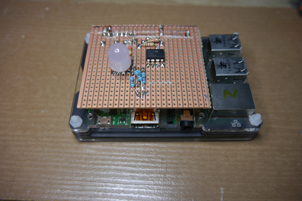
If you want to completely follow the whole HAT design process, you now have the option to make the transition from breadboard to proper circuit board. The Raspberry Pi Foundation specification also sets the physical properties of the board, right down to the radius of the rounded corners and the inclusion of slots for the camera and display cables. For prototyping, you probably needn’t worry about this too much; a simple stripboard design is available in the GitHub repository for this tutorial, and is pictured in the main image. If you want to take things even further, the marvellous Fritzing CAD software has a built-in PCB template that can help you produce a final design suitable for manufacture.
Code listing
from gpiozero import RGBLED
from time import sleep

led = RGBLED(22,27,17)

led.on()
sleep(0.5)
led.off()
led.red = 1
sleep(0.5)
led.red =0
led.green=1
sleep(0.5)
led.green = 0
led.blue = 1
sleep(0.5)
led.blue=0