The latest release of the Raspberry Pi Desktop x86 operating system alongside Raspbian Stretch for Raspberry Pi includes a new GPIO expander tool. Now you can easily run GPIO programs from your PC by simply plugging in a Pi Zero with a single USB cable and no SD card is required. It’s handy for prototyping, and can be really useful in coding clubs, libraries, and schools where the conventional Pi setup isn’t possible. It has limitations, but it’s ideal for lots of GPIO projects, such as many of the GPIO Zero ones you’ll find in The MagPi.
You'll need
- PC (desktop or laptop running Windows, Mac or Linux)
- Pi Zero (any model) with GPIO header
- Debian Stretch with Raspberry Pi Desktop on USB stick
- micro USB cable or Pi Zero USB Stem
- LEDs and a button
- 3D Xmas Tree
- SnowPi
This tutorial first appeared in The MagPi 67 and was written by Ben Nuttal
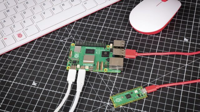
The GPIO expander tool means you can connect a Pi Zero (original, W, or WH) to a regular PC with just a micro USB cable, no SD card required, and control the GPIO pins. The easiest way to get it working is by live-booting the Raspberry Pi Desktop x86 OS on your PC. Remember, when live-booting, once you shut down, just remove the USB stick and you can return to your usual operating system and get back to your boring spreadsheets or whatever.
Boot into the Stretch release of Raspberry Pi Desktop, which comes with everything you need, ready to go. Plug in your Pi Zero and you’ll be prompted to select a role for the device. Select ‘GPIO expansion board’ and continue. It will take 30 seconds or so to flash it, then the dialogue will disappear.

Once the dialogue disappears, that means your Pi Zero is ready. Try pinging it just to be sure it’s connected. Open a Terminal and type:
ping6 fe80::1%usb0
This is the Pi Zero’s IPv6 address. You should see some responses, so press CTRL+C to stop pinging. If you can’t connect to it, try plugging it back in and trying again. You’ll need to define two environment variables to set this as the default route for GPIO commands. Type:
leafpad .bashrc &
This will open a simple notepad editor with your user’s Bash configuration. Scroll to the bottom and, on new lines, add:
export GPIOZERO_PIN_FACTORY=pigpio
export PIGPIO_ADDR=fe80::1%usb0
Save the file and close it. Now close the Terminal window and open up a Python editor or shell (such as Thonny or IDLE). Connect up an LED or a simple LED board like a Pi-Stop, and write the following code to flash a single LED (you’ll need to know which GPIO pin number it’s connected to – we’re using GPIO 17):
from gpiozero import LED
led = LED(17)
led.blink()
You should see the LED on the Pi Zero blink on and off continuously. That’s just the start! Take a look at the GPIO Zero documentation, as well as plenty of tutorials in The MagPi for lots of different projects you can do with GPIO Zero.
Using two Pi devices together
As well as using GPIOs from your PC, you can connect a Pi Zero to another Raspberry Pi and use two sets of GPIOs together, controlled within the same script. This is similar to the principle of remote GPIO, but instead of using Pi devices over a LAN (local area network), where each Pi has to be running Raspbian from an SD card, this method again just requires a Pi Zero and a USB cable.
Now boot a Raspberry Pi (e.g. a Pi 3) running the latest Raspbian Stretch. The Pi Zero tool is not pre-installed in Raspbian, so you’ll need to install it. Open a Terminal and type:
sudo apt install usbbootgui -y
When it’s booted, connect a Pi Zero with a USB cable and this time, instead of setting the default pigpio address and pin factory, you’ll define that within the code. Open a Python editor and type out:
from gpiozero import LED, Button
from gpiozero.pins.pigpio import PiGPIOFactory
from signal import pause

pizero = PiGPIOFactory('fe80::1%usb0')

btn = Button(17)  # button on Pi 3
led = LED(17, pin_factory=pizero)  # led on pi zero

led.source = btn.values

pause()
Here you have a button connected to GPIO 17 on the Pi 3, and an LED connected to GPIO 17 on the Pi Zero, which is connected via a USB cable. When the button is pressed, the LED lights up. Again, this is the simplest of examples, but it demonstrates the principle of controlling devices attached to two different Pis.
A better use for this would be to use two HATs or other add-on boards which use the whole pin header; for example, the Pi Hut 3D Xmas Tree and the Ryanteck SnowPi. The Christmas tree uses all available GPIO pins for its LEDs, and SnowPi uses nine of its own. But of course, you can simply place one board on the Pi 3, and another on the Pi Zero and when creating the relevant GPIO Zero device objects, use the remote pin factory for one:
tree = LEDBoard(*range(2, 28))
sp = SnowPi(pwm=True, pin_factory=pizero)
If you want to run a Python script on boot (using @reboot in cron), there’s a trick you can use to wait for the Pi Zero to be booted over USB before you try to control it. The PiGPIOFactory connection will fail with an OSError if the Pi Zero is not available, so you can just keep trying that until it works using a try/except block:
pizero = None
while not pizero:
    try:
        pizero = PiGPIOFactory('fe80::1%usb0')
    except OSError:
        sleep(1)
…then proceed to create the SnowPi object on the pizero pin factory.
As you can see in our final code, we turn the tree star LED on, have the tree’s red LEDs randomly flicker, and have the SnowPi’s LEDs blink on and off.