The Party Popper idea was first presented as a fireworks day workshop at the Milton Keynes Raspberry Jam, and then expanded for The Girls Day at Bletchley Park National Museum of Computing, covered in The MagPi 77. The contraption enables us to remotely trigger a party popper (or poppers) with some simple Python code on our Raspberry Pi. We will first need to create a holder for our party popper, which we can design in a 3D modelling app and make with a 3D printer. Then, we will be firing it using the action of a low-cost servo.
This tutorial was written by Mark Vanstone and first appeared in The MagPi 81. Sign up to our newsletter to get a free digital edition of The MagPi every month. Or subscribe in print and get The MagPi delivered to your door. 12-month subscribers get a free Raspberry Pi computer. Mark is an educational software author from the nineties, author of the ArcVenture series, disappeared into the corporate software wasteland. Rescued by the Raspberry Pi!
Click here to download the source files for 3D printing the Party Popper.
Build a Party Popper: Let’s start from the end
Normally when introducing a tutorial, we would start with the basics and build up the idea, but in this case we need to see what we are aiming at, and then go back and put together each part of the build. This is how we approached designing the launcher: we decided what needed to happen and then worked on each part until it satisfied the requirement. So here is our impression of monkeys writing War and Peace, but we’ll miss out the bits that didn’t work. See the main image for the fully assembled launcher, and we’ll go through the parts that it’s made of.

The holding device
The launcher was designed using Blender and then 3D-printed. The source files are all available on GitHub if you want to play with the design. First, let’s look at a way of holding a party popper; it will need to be held straight with access to the firing string. We have a tube shape, with the inside being a width to mimic the popper shape, and a hole for the ‘handle’ to go though. The base of the tube is quite thick, to enable a post to be attached and be a firm fit.
The base
The base could be printed out in one piece, but we found that laying the main part on its side made for a better construction for the servo to be mounted into. An interlocking cross-piece can then be printed to provide some stability to the base and stop it from falling over. When printing these pieces, you may need to adjust the wall widths so that they fit snugly together, but are not too tight. The base also has a hole, as with the holder part, so that a post can be attached.
The post
This is where it all comes together. The post is just a cylinder to attach the holder to the base. It does have a flat edge along its length, but that is only so that it sticks well to the 3D printer bed while it is printing. With this design, all four parts can be printed in a single print and then packed up into a small box, such as a plastic business card holder, with the other components for the build, which makes it ideal for workshops. It also provides an extra dimension of making for the workshop if no assembly instructions are provided.

3D print designing
So, we have covered what the 3D-printed parts are, but not how they were made. If you have not designed your own 3D parts before, it’s not difficult. You need a 3D modelling app; there are several free and paid-for options. Our favourite at the moment is Blender, because it’s free and we have followed its development for years; the makers have just made the beta of 2.8 available, and it rocks! Any modelling app that exports .obj or.3ds files or similar will be fine, as long as that is compatible with your 3D-printing software.
Blender
3D modelling on the Raspberry Pi is a bit limited due to the hardware graphics support. You can install Blender with
sudo apt‑get install blender
There are also a few other options, such as 3D Slash.
Making the shapes
If you are new to 3D modelling, try to keep the objects you make fairly simple to start with. This build is a good example of just using basic shapes. We have a few rectangles, a long cylinder, and short, wide cylinder. The way to make the various holes in these shapes is to create a solid shape, then make a shape that you want to cut out. Then you can use a Boolean tool to subtract or cut out the second shape from the first. When you have completed your design, export the model in a suitable format. Try a few different ones, as the results may vary when you import into your 3D printing software.

3D printing
Due to the way the parts are laid out, there are no significant overhangs, other than the small post holes, which means you shouldn’t need to clear away any supports or extra stuff. We used PLA filament on a very cheap, self-assembled printer. As a side note, if you want to find out all about how 3D printers work, get a DIY version and if you are feeling brave, a really cheap one with foreign instructions. By the end of the process of getting it working, you will know all about every component!

Heavy-duty servos
To start with, the obvious thing was to reach into the drawer and pull out whatever gizmos could be found that might be able to pull a party popper string. We tried a motor, but there were issues around needing gears, a suitable driver module, and mounting it securely. We then found one of the little blue 9 g servos. It tried, it really did, but in the end we had to accept that it was not going to do the job. We found a lone HS-422 servo in the drawer, reworked the stand, and found a better result. Since then, we have found MG 996Rs are very similar in size and effect for this application.
Tip! Analogue servos
You can use analogue servos for this, but because the GPIO is digital, you may find that working out the angles is more difficult, as the output will give some weird results.
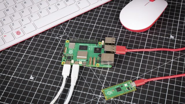
Plugging it in
It is possible to wire the servo directly to the Raspberry Pi GPIO pins with three male-to-female jumper leads. Take a look at Figure 1 for where the wires go. A word of warning: although plugging in these electronics into these pins with the Pi running shouldn’t cause it damage, if you get it wrong, the outcome could be very different, so always power down the Pi before wiring up the GPIO pins, and check they are correct before switching back on. Once everything is hooked up, we can test the servo and get it moving.

Testing 1, 2, 3
We can write a simple Python program to make the servo turn. See party_popper.py for the listing. We can write it using IDLE 3 or, if you prefer, another editor provided with Raspbian. We set up GPIO 2 (which is physical pin 3) to PWM (pulse-width modulation) mode and start the output. We then have a function to change the angle of the servo arm. We calculate the pwm value we need from the angle and change the duty cycle of the servo, wait for it to move, and then reset that value. By changing the value in the setAngle() call below this function, we will see the servo arm moving when we run the program.
See also:

Using the angles
It will depend how the armature of the servo is set, and probably a few other factors, that will define what angles are needed for the servo to move and pull the popper string far enough to set it off. If you mount the servo in the base so that the string can be attached to the end of the armature and as it turns, it pulls the string straight down (or as straight as possible), then you just need to find the angle at which the length of the string is shortest, and then the angle at the armature’s lowest.
Fire in the hole!
If everything is wired up correctly, your servo is set to the starting position and slotted into the base of the holder, the string is attached tightly to the armature, then we are ready to fire our party popper. Run the code with the setAngle() parameter set to the end angle we need, and in a couple of seconds the servo should spring into life, pulling down on the string with several kilograms of force. Before you know it, there should be a loud pop and a nice pile of streamers to clear up!
import RPi.GPIO as GPIO
from time import sleep

GPIO.setmode(GPIO.BOARD)
GPIO.setup(3, GPIO.OUT)
pwm=GPIO.PWM(3,50)
pwm.start(0)

def setAngle(angle):
    duty=angle/18+2
    GPIO.output(3, True)
    pwm.ChangeDutyCycle(duty)
    sleep(1)
    GPIO.output(3, False)
    pwm.ChangeDutyCycle(0)

setAngle(0)

pwm.stop()
GPIO.cleanup()